Modelling a Puzzle
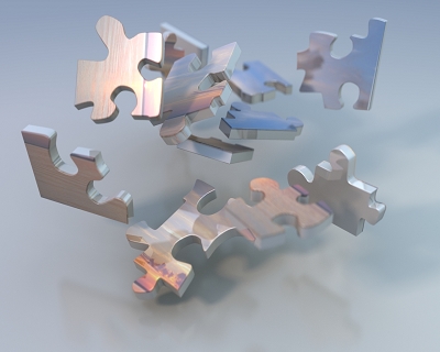
Puzzle Art
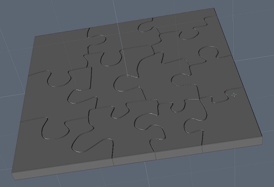
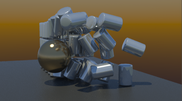
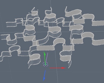
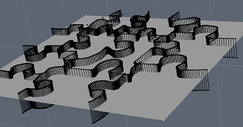
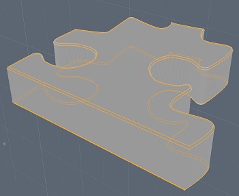
This tutorial outlines how to create the model of the objects shown here.
This tutorial is intended not for the absolute beginner with modo, but for someone who is at least familiar with all common 3D terms and the modo interface. The steps here should be easy to follow for most users of modo after familiarization with its user manual.
To start, an outline for the approach used here is to stencil into a plane the outline of the pieces, extrude the pieces up and then smooth out the edges with some bevels. So, create a flat rectangle to outline the puzzle you would like. You can just as easily use a different shape, an oval or something specific.
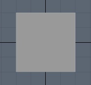 |
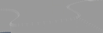
Create your outlineI used a simple square for my puzzle, so create the shape you want for yours. This one is on the XZ axis so it can be extruded up and layed flat on the Y-axis. Outlining the puzzle piecesThis is very easy to do using the spline tools to draw some curves for the edges of the pieces. put your plane into the background layer so its outline is visible. |
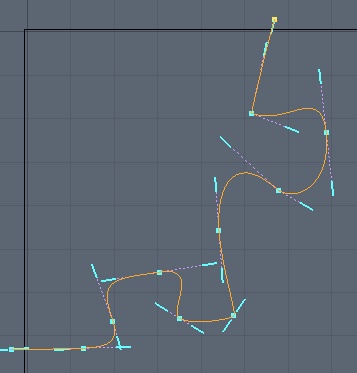 |
Bezier pieceHere is an example of creating the piece for the top left corner. The bezier has been tacked down to outline a nice puzzle edge. Try to create your pieces evenly spaced within your whole puzzle and most of your pieces should be about the same size. It is also important to try to make the connection tabs realistic. Most puzzles cannot have there pieces pulled apart so your connecting tabs should interlock well between the majority of your pieces. |
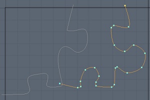 |
Using CurvesThe curve tool is another type of spline you might want to use for your puzzle edges. Use either the curve or beziers or even the sketch tool to outline the edges of each of the puzzle pieces. Make sure you overlap the edges of each piece so that you can later stencil them onto each other and the background. |
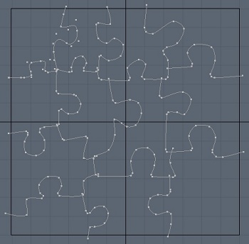 |
Completing the puzzle edgesOutline the rest of your peices using your preferred curve tools. Make whatever adjustments are needed once you have the whole puzzle visible as well. The overlap is visible still here for each curve which will be used to join up the pieces. |
 |
Extrude the edgesNext, we need to stencil our edges into our puzzle plane, so we can first extrude the curves on the Y-axis to get some depth. Extend will NOT work here since it works only on the control points and not on the smooth mesh of the curve. Setup the stencil layersStencil into the plane by putting the plane in the background layer with the newly extruded edges overlaying it. You may need to move the edges or plane up or down to ensure they overlap each other. |
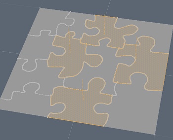 |
StencilPerform a stencil boolean from the menu: Geometry -> Boolean -> Solid Drill… Stencil You should end up with a nice flat puzzle. If you properly overlapped all the edges, your will also have each of the pieces as polygons since the edges cut through each other when you make the stencil. |
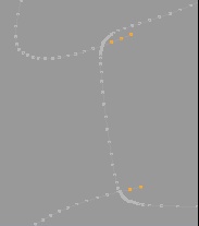 |
Remove stray pointsSelect the stray points that overlap each puzzle piece and delete them. Each of your curves will have have these at each end (exept outside your puzzle of course). Create your piece layersYou need to put your pieces into separate layers now so they can be extruded and kept attached to only there own surface polygon. You don’t want the edges to join between pieces again. |
Extrude your puzzle pieces
Select all your layers and give them some depth by extrude all the pieces.
Bevel the surface polygons on each piece
Now, we need to start smoothing out the pieces so we want to have some bevelling on the edges. Select the face polygons of each piece, select the back faces as well if you want them to ahve the same smooth bevel.
Your bevel should have a inset and shift about equal. A small bevel will be suttle with less problems on the overlapping and high vertex count corners.
Note: Often, while using the bevel tool with in inset, the inset edge will have overlapping points. These can be removed manually afterward to unwrap the corners and bevel edges or often it helps to reduce the number of points on inside corners so they do not overlap as quickly when you add the inset bevel. Also, you cna perform the bevel on all pieces at the same time if you wat them all the be identical without need to preset the toolpipe or write down your bevel settings.
 |
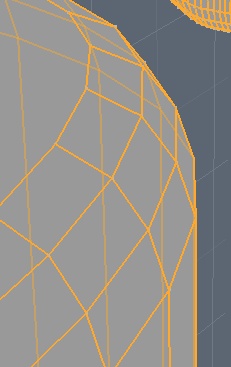
Edge Boundary
You also need the next edge loop selected beside the main face polygon so SHIFT-Left Arrow to add the next edge loop to the selection. Then SHIFT-Right Arrow a few times to move back the other direction and get the other side’s next edge loop selected. |
 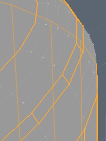 |
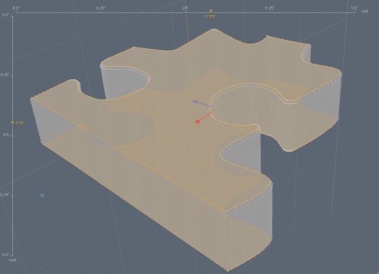
Smoother BevelFinally, we need to smooth out these edge loops more so we can now bevel the selected loops. Bevelling the edges will add geometry for a more detailed round edge. The bevel follows the existing contour so will provide a nice round bevel. You can set the round level according to the amount of detail you want. The left side shows bevelling at 0 and at 2. Note: You may have to fix some overlaps on the polys after the bevel to correct the drawing on the N-Gon flat surface poly. |
That should leave you with a nice looking puzzle with all the edges smoothed and each piece in its own layer, ready to be animated.